niawellwww.niawell.com
DC LoadbankPDL
DC Loadbank

FEATURES

  • Wide input voltage range (500 ~ 10)
  • High power in a small volume
  • Precise constant current control with accuracy less than 0.5 A
  • Separate monitor and control section from the device
  • Ability to test batteries under real load
  • Real-time reporting and plotting during the test
  • Ability to test various batteries (Nickel-Cadmium - Lead-Acid - Lithium)
  • Dynamic discharge technology - maximum current at all voltages
  • Support for parallel operation to increase power capacity

APPLICATIONS

  • Industrial battery and high voltage testing centers
  • Power plants
  • Telecommunications industries
  • Rail and metro systems
  • Oil and gas industry
  • Military and aerospace industries
  • Data centers
The PDL series DC loadbank is an advanced tool for testing, discharging, and evaluating the performance of various industrial batteries. This device, capable of operating in three operating modes CC (constant current), CP (constant power) and CR (constant resistance) and with a wide voltage range from 10 to 500 volts, is ideal for testing nickel-cadmium (Ni-Cd), lead-acid and lithium batteries. The compact design and high power density make it easy to use in space-constrained environments. Precise current control with accuracy of less than 0.5 A ensures a stable and reliable discharge. The Central Supervision Unit (CSU) monitoring and control module enables remote monitoring and system management. Test results can be viewed, saved and edited on a personal computer via the Niawell CSU Logger software provided with the device. In addition, comprehensive data logging, real-time charts and generation of PDF reports enable precise and professional analysis of battery performance. The simple user interface, quick setup and stable operation make the PDL a smart choice for industrial testing centers.

MODEL ENCODING

PDLSeries
-
500Voltage
-
40KPower (40KW)
Model
PDL-500-40K
PDL 500-80K
Electrical specifications
Input voltage range
10 ~ 500
Output power
40 KW
80 KW
Maximum current
110 A
200 A
Auxiliary input power
AC 220V, 50HZ, 6A
Cooling method
Vertical airflow by fan
Modes
Current Mode - Power Mode - Resistance Mode
Minimum load step
0.5A (Current Mode), 100W (Power Mode), 0.1Ω (Resistance Mode)
Type of power switch
Power IGBT & MOSFET
Protections
Fan failure - Thermal cut-outs - Overload protection - Emergency stop button - Reverse Polarity
Physical specifications
Weight
55 KG
85 KG
Dimensions (W×L×H) cm
35×78×50
46×95×75
Environmental conditions
Temperature range (°C)
0-50 °C for indoor use
Storage and Transportation
-40°C to +70°C (-40°F to +158°F)
Humidity
5% – 95% RH, non-condensing
Operating Altitude
3000 m (10000 ft)
General Features
Testable Items
Batteries & DC Power Supplies
Capabilities
Graphing – Centralized control remotely via network cable
Test Storage
Stores last 12 tests for review with PDF export
Items
Accessories
CSU - Power Cable with connectors - Auxiliary power supply - Network cable - Cable for log - Case for auxiliarys parts - Cover

Chart

Graph.png

Practical Example

In a test scenario, the PDL device is connected to the battery and the warning thresholds for current and voltage are preset. After the discharge process begins, the device maintains the current at the set value in constant-current mode (CC). As the voltage gradually decreases and reaches the warning level (a value slightly above the cut-off voltage), the device triggers an alarm. If the voltage continues to drop and reaches a critical level that risks deep discharge of the battery, the PDL automatically stops the discharge process to prevent damage to the battery.</br>In case of a temporary power interruption, the device resumes the test process from the same point after power is restored. All recorded data are stored in the device memory and can be easily transferred to a computer via the Niawell CSU Logger software and viewed and managed as PDF.

Example.png

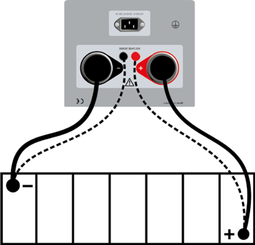
For accurate measurement of battery voltage, especially in applications with long cables or high currents, it is recommended to use separate sense lines (sense lines) to compensate for voltage drop.